Trunk Configuration is used to apply settings to specific hardware ports. After setting up a new trunk group, use Trunk Configuration to assign trunks into the trunk groups. Both Digital and Analog trunks are configured in Trunk Configuration. SIP Trunks are configured separately (see Add a SIP Trunk (SCP)).
- Login to Global Administrator (see Login to Wave IP Global Administrator).
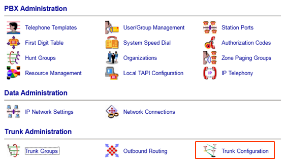
- Select Trunk Configuration.
- The Trunk Configuration app has an entry for every hardware trunk port on the Wave. The analog trunk ports (two on the IP 500 and four on the IP 2500) on the Wave are always listed. There will also be entries for any additional trunk cards.
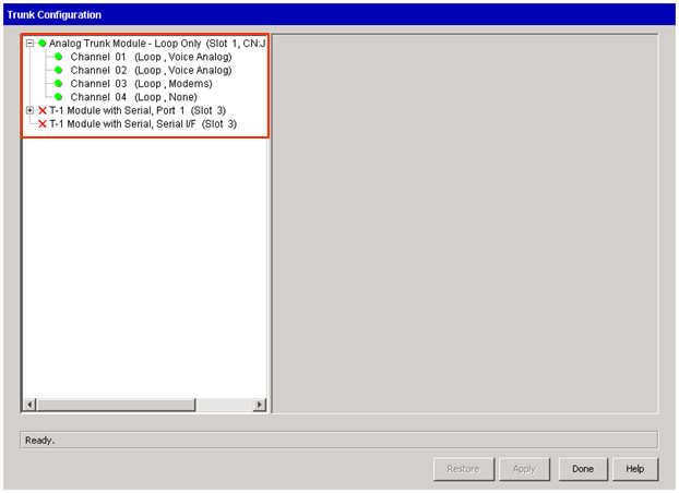
- Click on an individual trunk to change settings. Change multiple trunks at once by clicking on multiple trunks while holding the Shift key or the CTRL key to select non-consecutive trunks.
- Analog trunks are generally simple to configure. Digital trunks have more options to configure.


- Each channel on a analog trunk card is a separate trunk and may have different settings.
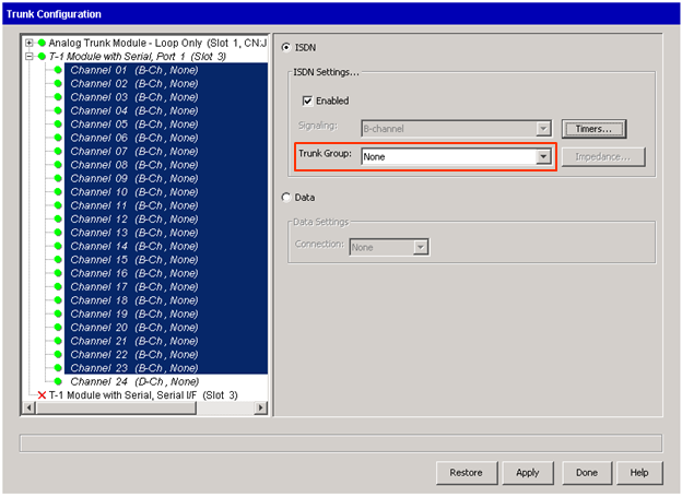
- Click on any channel and settings will appear on the right. The first step is to make sure the Enabled checkbox is checked.
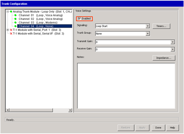
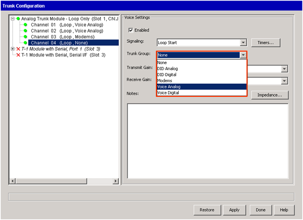
- The only required setting is the Trunk Group. Click the dropdown box and apply the appropriate trunk group (by default the Voice Analog group). This controls the inbound and outbound settings for all trunks assigned to the trunk group. See Configure Trunk Groups.
Note: The outbound hunt order of trunks in a trunk group is controlled by the order of ports in the Trunk Configuration view. TO make sure an analog trunk is at the top of the hunt order make sure it is plugged into the highest channel on this list (that is in the hunt group). For example, Channel 01 and Channel 02 are both listed in the Voice Analog group. Channel 01 is at the top of the hunt order.
- Most analog trunks will be loop start. To enable a ground start trunk choose the Signaling dropdown box and change to Ground Start. It is also possible to adjust individual timers for analog signaling. Normally, there is no need to adjust those settings.
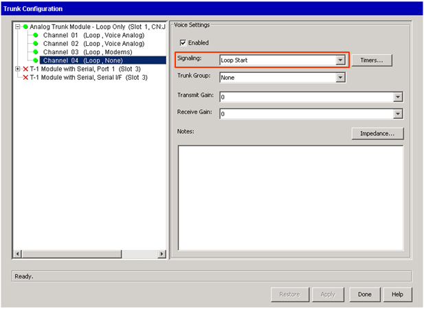
- Other settings include gain settings to adjust volume levels if there are problems on the trunk. The impedance button should only be adjusted in collaboration with Vertical Support.
- Click Apply or Done to save settings.


- Digital trunks are bundled into their circuit (either T-1 or E-1). There are common settings for the circuit as well as individual settings for each channel.
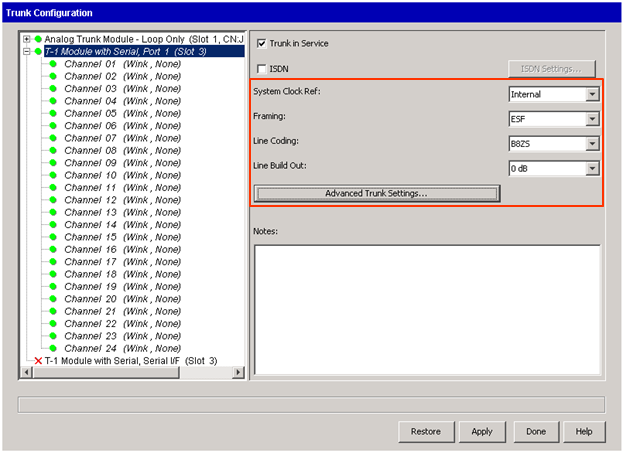
- Control settings for the entire circuit by clicking on the Module.

- A T-1 uses careful timing between each endpoint of the circuit to send signals. When connecting to a carrier, this setting will almost always be External Primary (the carrier sets the clock signal). When setting up a Tie line between two systems one side should be Internal and the other will be External Primary. External Secondary is only used if a system has more than one T-1. The secondary external clock source will only be used if the primary fails.
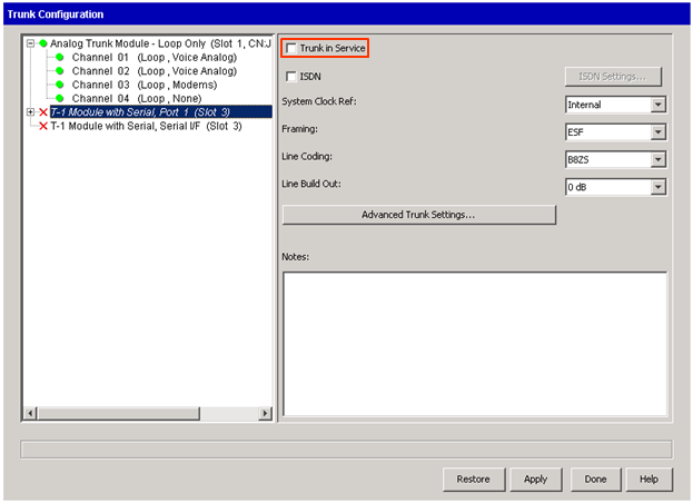
- Framing and Line Coding are set depending on the carrier's settings. Most commonly, the carrier will use ESF and B8ZS. (for a Tie line, both ends must simply be set to the same settings.)
- Click on Trunk in Service to bring the T-1 into service. There are two major types of T-1 signaling: PRI, Robbed Bit T-1.
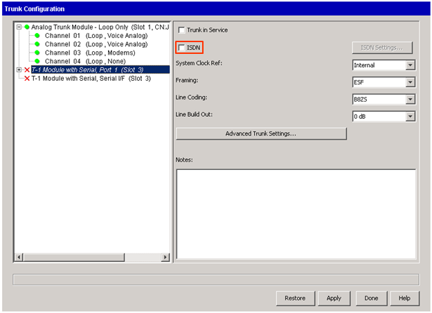
Setting Up A PRI - The more common setting today is a PRI. For PRIs, enable the ISDN checkbox. Then click on the ISDN Settings box.
- Choose the switch signaling (provided by the carrier).
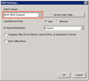
- The User/Network Mode should generally be set to User unless this connection is being used as a Tie line to another system. Then one of the two systems will need to be set as the Network.
- Only click the "Outgoing Caller ID Provided by Central Office," if the carrier requires that they will send CallerID. If this is the case, no custom CID settings will work.
- If the carrier supports Calling Name, check the "Send Calling Name" box.
- Click OK to apply these settings.
- The other step with a PRI is to set the trunk group for the channels.
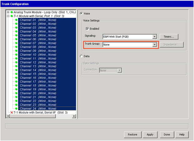
- Select all of the channels on the circuit that will be in a trunk group (usually all 23 channels on a PRI will be in the same trunk group, but occasionally the circuit may be split into multiple trunk groups.) Set the Trunk Group with the dropdown box (the default group would be Voice Digital.)
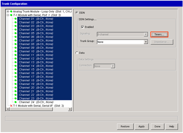
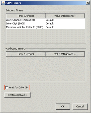
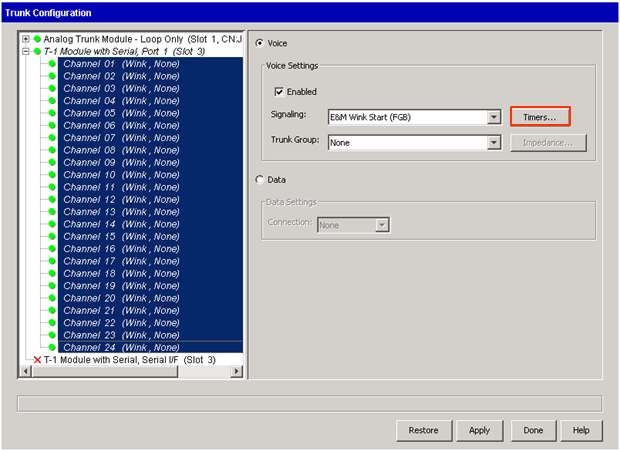
- To enable incoming Caller ID on PRIs, click on Timers.
- Click on the "Wait for Caller ID" checkbox. Leave all other timing settings alone unless directed by Vertical Support or the carrier.
- Click Apply or Done to save settings. Make sure to make test calls inbound and outbound to verify the circuit is working.
- Choose the switch signaling (provided by the carrier).


- Setting up a Robbed Bit T-1 involves using fewer settings.
- The same settings including clock, framing, and line coding are used for a robbed bit T-1.
- Select the signaling for this T-1 circuit. This information will be provided by the carrier.
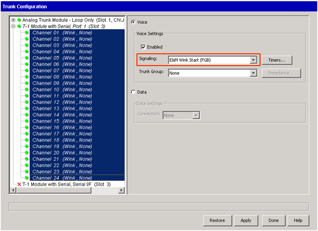
- Select the channels to go in a trunk group (usually all 24 channels on a T-1 will be in the same trunk group, but occasionally the circuit may split into multiple trunk groups.) Set the Trunk Group with the dropdown box (the default group would be Voice Digital.)
- The Timers button allows adjustments to individual timing settings. It the carrier provides custom timing settings for their signaling use this button to make adjustments. Otherwise, leave it alone.
Note: It is possible to use the Loopback testing applet in Wave to receive carrier signaling. This can sometimes provide the correct Signaling and Timing settings if the carrier is not providing the information.
- Click Apply or Done to save settings. Make sure to make test calls inbound and outbound to verify the circuit is working.


